
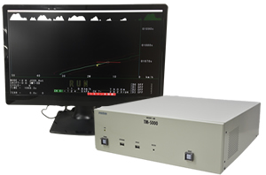
- In response to severe regulations on exhaust gases and fuel evaporation, a Driver’s Aid controller can be easily connected to an automobile measuring system, such as an exhaust-gas measuring device.
A driver can easily drive an automobile while watching a specified operation mode on an indicator.
A system can be configured with VGA-compatible displays of various sizes. It can also be used at an inspection line or for research and development.
Features
-
Real-time display of various measurement data
If a signal is input from external equipment used in vehicle testing, various measurement data, such as engine revolutions of a vehicle and intake pressure, can be displayed on an operating screen in real time.
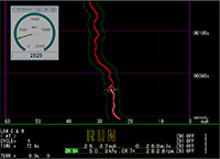
Arbitrary measurement data can be displayed with an analog meter. A display position and a size, etc. are also easily changeable. -
Customize screen display
The color and thickness of a display line, such as vehicle-speed indication patterns, etc., and the color and shape, etc. of an actual vehicle speed marker are made available for use. It becomes possible to customize a display to make it easily visible to a driver. -
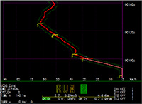
Easy to understand shifting timing
To notify a driver of timing through sounds and blinking displays beforehand prior to the timing of changing the speed of a shift, the timing in which the driver changes speeds is easy to understand. -

Remote function
A Diver’s Aid can be remotely controlled from an external PC.
It responds to the transfer of mode data and the acquisition of logs of vehicle-test results. -
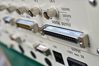
External output function
It is also possible to cause a recorder (a pen recorder, etc.) to draw a driving status in real time during vehicle testing, and to control external equipment that is used in vehicle testing. -
Respond to customers needs.
You can also add your own features to meet your needs.
Please consult with us first.
Specs
| External dimensions | 414(W)×131(H)×453(D) mm (Projection things are not included.) |
|---|---|
| Mass | Approx. 12.5kg |
| Use environment |
|
| Power supply | AC100V±10% 50/60Hz Approx.200VA |
| Display part | 1024×768dots(XGA) / 1920×1080dots(FHD) LCD compatible with analog RGB of general-purpose can be used. DVI compatibility is optional. |
| Operation part | Wired, wireless, and portable type remote control unit to selection is possible. |
| Analog vehicle speed input | Maximum vehicle speed 200km/h Input voltage 0.5 / 1 / 2 / 5 / 10 / 20 / 50V (selected by software) Zero point and Full-scale adjustment are possible (soft processing). Input isolation. |
| Analog output | Full-scale 10V×6 channels (Actual vehicle speed, Indicating vehicle speed, Upper and Lower limit of vehicle speed etc.) |
| Auxiliary memory storage | 2.5″SSD (Approx.200GB) |
| Standard interface | Front panel USB×2 (for keyboard, mouse) Rear panel USB×3 (for keyboard, mouse, maintenance) LAN 1000BASE-T |
| Pulse input of vehiclespeed |
|
| Digital Input/Output |
|
| Warning sound | The driver is notified detection Error and Shift gear position by sound. (When using the receiver RC-441 for an operation part) |
| Auxiliary analog input | 2 channels Input voltage 0.5 / 1 / 2 / 5 / 10 / 20 / 50V (selected by software) Input isolation |
Option
Signal cable
Cable to connect Driver’s a Aid and peripherals.
We will manufacture necessary cables according to customer’s system.
We will manufacture necessary cables according to customer’s system.
Rack-mount Panel (With video Splitter ・No video splitter)
It is a panel that enables installation on a 19-inch rack.
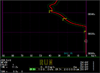
Overall display function of driving mode
All vehicle-speed patterns in a selected run mode are displayed in the upper part area of an operating screen.
It is possible to check operating positions and operational error locations, etc. in all patterns during operation.
It is possible to check operating positions and operational error locations, etc. in all patterns during operation.
Vehicle speed scale magnified display function
The enlarged view of a mode is executed by making settings for the arbitrary upper limit value of scale.
When an actual vehicle speed reaches a set value, the movement of a vehicle-speed marker is fixed in the direction of vehicle speeds. Displayed and indicated vehicle-speed patterns begin to scroll in the direction of vehicle speeds. They are automatically switched accordingly.
The unit of a set value is automatically switched according to a pattern.
Application example
Application example of Driver’s Aid
- Automobile running mode exhaust gas test
- Running mode fuel consumption rate test of automobile
- Driving mode gradient load test for automobiles
